1 - Introduction to Radar Systems - Fundamental Concepts of Radar Systems

Introduction to Radar Systems: From Fundamentals to Advanced Concepts
This article is based on the first three sections of the "Introduction to Radar Systems" lecture series prepared by MIT Lincoln Laboratory. The aim is to convey the fundamentals, operating principles, and historical significance of radar technology in a technical yet comprehensible manner. It is intended for newcomers to radar engineering, electrical-electronics engineering students, and technical professionals.
1. Why Radar?
War is chaos. In the words of Dwight D. Eisenhower: "In war, all plans are useless, but planning is indispensable." This paradox perfectly summarizes the uncertainty on the battlefield. During the Normandy landings, paratroopers landed kilometers away from their targets, an unexpected Panzer division awaited at Omaha Beach, and amphibious tanks sank in high waves. All these unforeseen situations are concrete examples of the concept known as the "fog of war."
Radar was developed to disperse this fog. For a commander to see obstacles ahead, to know the location of enemy forces, to detect approaching threats in advance—all of these became possible with radar technology.
1.1 What Can Radar Do?
Among electronic sensing systems, radar possesses unique capabilities:
Surveillance: Detecting the presence of targets in the air, at sea, or on land
Tracking: Continuously monitoring the movement of detected targets
Target Identification: Determining the type and characteristics of the target
Mapping and Reconnaissance: Terrain imaging, moving target detection
Air Traffic Control: Safe flight in civil and military aviation
Missile Guidance: Precision targeting systems
1.2 Fundamental Advantages of Radar
Long Range: While the human eye can see 15-20 km under the best conditions, radar can detect targets hundreds of kilometers away.
Day/Night Operation: Unlike optical systems, radar works in darkness as well.
All Weather Conditions: Fog, rain, clouds—radar can "see" through them.
3D Positioning: The distance, angle, and altitude of a target can be measured simultaneously.
Resistance to Countermeasures: It is relatively resistant to electronic jamming and deception.
2. Historical Turning Point: Chain Home and the Battle of Britain
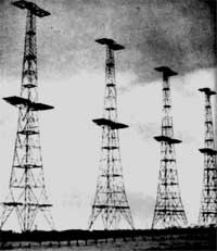
In 1936, Great Britain realized that war was inevitable. The government took action to establish an early warning system. The result: Chain Home—the first operational radar network in history.
2.1 Technical Specifications
Parameter | Value |
|---|---|
Frequency Range | 20-30 MHz |
Wavelength | 10-15 meters |
Peak Power | 350-750 kW |
Detection Range | 160 km (100 miles) |
Pulse Repetition Rate | ~15 pulses/second |
The system consisted of massive antenna towers installed at 21 different locations. Each tower was approximately 110 meters (360 feet) high. The antennas were simple wire structures made up of 8 dipole arrays—because at that time, powerful transmitters could only be produced at these frequencies.
2.2 Strategic Impact
In the summer of 1940, Germany tried to force Britain to surrender by bombing. The goal: to gain air superiority and then launch a land invasion.
Britain's approximately 1,400 fighter aircraft were dispersed across different airfields. Without radar, enemy aircraft could not be detected until they came within visual contact range (10-15 km). This would not leave enough time for defensive aircraft to take off, gain altitude, and intercept the enemy.
The Chain Home system completely changed this equation:
Early warning from 160 km away
Timely takeoff of fighter aircraft
Concentration of forces at strategic points
Numerical parity with German attacks
Result: Germany could not achieve air superiority. The invasion of Britain was postponed indefinitely. The course of World War II changed. If Britain had fallen, the base the Allies would use to liberate Europe would have been eliminated.
An interesting detail: The Germans bombed the Chain Home towers several times, but never fully understood that these were a critical radar system.
3. Fundamentals of Electromagnetic Waves
Radar is a technology based on electromagnetic waves. Therefore, before understanding radar systems, it is necessary to grasp the fundamentals of electromagnetic wave physics.
3.1 How Is an Electromagnetic Wave Generated?
In its simplest form: when you accelerate an electric charge, you produce an electromagnetic wave.
This process works as follows:
A stationary charge creates a static electric field.
When you move (accelerate) the charge, the electric field changes over time.
The changing electric field creates a magnetic field.
The changing magnetic field, in turn, creates an electric field.
This mutual generation produces a wave that propagates through space.
James Clerk Maxwell mathematically formulated these relationships in the 1860s. Maxwell's equations define the fundamental laws of electromagnetism and form the theoretical foundation of all electromagnetic technologies, including radar.
3.2 Wave Properties
Every electromagnetic wave is defined by three fundamental parameters:
Wavelength (λ): The distance between two successive peaks. Measured in meters.
Period (T): The time it takes to complete one full wave cycle. Measured in seconds.
Frequency (f): The number of wave cycles per second. Measured in Hertz (Hz).
These three parameters are related by the speed of light (c):
f = c / λ
Here, c ≈ 3 × 10⁸ m/s (speed of light).
3.3 Practical Frequency-Wavelength Relationships
Frequency | Wavelength |
|---|---|
1 GHz | 30 cm |
3 GHz | 10 cm |
10 GHz | 3 cm |
30 GHz | 1 cm |
This relationship leads to a critical result: high-frequency radars have shorter wavelengths and can operate with smaller antennas. For this reason, missile seekers operate at high frequencies—they require antennas small enough to fit into the nose of a missile.
3.4 Phase and Interference
Phase expresses the position of a wave within its cycle. It varies between 0° and 360° (or 0 to 2π radians).
When two waves overlap, different results occur depending on the phase difference:
Constructive Interference (0° phase difference): The peaks of the two waves coincide. The amplitude of the resulting wave is twice that of each individual wave.
Destructive Interference (180° phase difference): The peak of one wave coincides with the trough of the other. Result: zero amplitude.
Partial Interference: At intermediate phase differences, partial addition or subtraction occurs.
This concept is critical in radar signal processing. For example, the coherent integration process combines signals using phase information.
3.5 Polarization
Polarization defines the orientation of the electric field vector in space.
Vertical Polarization: The electric field vec
is polarized vertically (up-down) to the ground.Horizontal Polarization: The electric field vector is polarized parallel to the ground (right-left).
Certain targets provide stronger reflection at specific polarizations. This feature is used for target identification and clutter suppression.
4. Electromagnetic Spectrum and Radar Bands
The electromagnetic spectrum covers a wide range from radio waves to gamma rays. Radars operate in the "microwave" region of this spectrum — roughly between 300 MHz and 100 GHz.
4.1 Radar Frequency Bands
During World War II, letter codes were assigned to radar frequencies for security reasons. This tradition continues today:
Band | Frequency | Wavelength | Typical Use |
|---|---|---|---|
VHF | 30-300 MHz | 1-10 m | Long-range surveillance |
UHF | 300-1000 MHz | 30-100 cm | Early warning radars |
L | 1-2 GHz | 15-30 cm | Air traffic control |
S | 2-4 GHz | 7.5-15 cm | Meteorology, marine radar |
C | 4-8 GHz | 3.75-7.5 cm | Meteorology |
X | 8-12 GHz | 2.5-3.75 cm | Fire control, imaging |
Ku/K/Ka | 12-40 GHz | 0.75-2.5 cm | High resolution |
4.2 Engineering Logic of Frequency Selection
Low frequencies (VHF, UHF, L-band):
Long range (low atmospheric attenuation)
Require large antennas
Low resolution
Use: Early warning, long-range surveillance
High frequencies (X, Ku, Ka-band):
Short range (high atmospheric attenuation)
High gain with small antennas
High resolution
Use: Missile seeker, imaging radar, fire control
5. How Does Radar Work?
The basic operating principle is surprisingly simple:
The transmitter generates a pulse of microwave energy.
The antenna focuses this energy in a specific direction and transmits it into space.
The energy travels at the speed of light and strikes a target.
The target reflects a portion of the energy back.
The antenna collects this reflected energy (echo).
The receiver detects and processes the very weak echo signal.
The signal processor calculates the target's position, speed, and characteristics.
5.1 Radar Block Diagram
A modern radar system consists of the following subsystems:
Waveform Generator: Determines the characteristics of the signal to be transmitted.
Transmitter: Amplifies the signal to high power (kilowatt-megawatt).
Duplexer: Allows the same antenna to be used for both transmission and reception.
Antenna: Focuses (transmission) and collects (reception) energy.
Receiver: Detects weak echoes at the microwatt level.
A/D Converter: Converts the analog signal to digital data.
Signal Processor: Pulse compression, Doppler processing, clutter suppression.
Detection Processor: Decides target presence/absence.
Tracking Processor: Tracks target movements, makes predictions.
Display: Presents results to the operator.
5.2 Range Measurement
Radar calculates the distance to the target from the round-trip time of the pulse:
R = (c × t) / 2
Where:
R = Range to target (meters)
c = Speed of light (3 × 10⁸ m/s)
t = Round-trip time (seconds)
The division by 2 is because the pulse must travel to the target and back.
Example: If the echo returns after 1 millisecond (0.001 s):
R = (3 × 10⁸ × 0.001) / 2 = 150 km
6. Radar Equation
The radar equation brings together all the factors that determine the system's detection capability. This equation is the cornerstone of radar engineering.
6.1 Basic Form
The received signal power depends on the following factors:
Transmitter Power (Pt): More power = stronger echo
Antenna Gain (G): Larger/more efficient antenna = better focusing
Target Radar Cross Section (σ): Larger/more reflective target = stronger echo
Distance (R): Received power decreases with the fourth power of distance (1/R⁴)
Wavelength (λ): Affects antenna gain
Losses (L): Cable, atmospheric, processing losses
6.2 Critical Observation: 1/R⁴ Law
The received power decreases with the fourth power of distance. This creates a dramatic effect:
Increase in Distance | Power Loss |
|---|---|
2 times | 16 times (12 dB) |
3 times | 81 times (19 dB) |
10 times | 10,000 times (40 dB) |
100 times | 100,000,000 times (80 dB) |
Therefore, to double the range, it is necessary to increase the transmitter power by 16 times or enlarge the antenna area by 4 times.
6.3 Signal-to-Noise Ratio (SNR)
The measure of detection capability is the signal-to-noise ratio:
SNR = Received Signal Power / Noise Power
For reliable detection, typically SNR ≥ 13 dB (about 20 in natural units) is desired.
7. Decibel (dB) Notation
In radar engineering, power ratios vary over a very wide range (from one millionth to millions). To manage these numbers, a logarithmic scale is used: decibel (dB).
dB = 10 × log₁₀(Ratio)
7.1 Values to Memorize
Natural Ratio | dB Value |
|---|---|
1 | 0 dB |
2 | 3 dB |
10 | 10 dB |
100 | 20 dB |
1000 | 30 dB |
0.5 | -3 dB |
0.1 | -10 dB |
0.01 | -20 dB |
Practical rule: Every 10 dB is a change of one order of magnitude (10 times). 3 dB ≈ 2 times.
8. Pulsed Radar Parameters
Most radars transmit short pulses instead of a continuous signal. The main parameters of this approach:
8.1 Basic Definitions
Peak Power (Ppeak): Maximum power transmitted during the pulse.
Pulse Width (τ): Duration of a single pulse (typically: microsecond-millisecond).
Pulse Repetition Interval (PRI): Time between successive pulses.
Pulse Repetition Frequency (PRF): Number of pulses transmitted per second (PRF = 1/PRI).
Duty Cycle: The ratio of the time the transmitter is on (τ/PRI).
Average Power: Ppeak × Duty Cycle
8.2 Sample Calculation
Parameter | Value |
|---|---|
Peak Power | 1 MW |
Pulse Width | 100 μs |
PRI | 1 ms |
Duty Cycle | 10% |
Average Power | 100 kW |
PRF | 1000 Hz |
9. Antenna Gain
The antenna is the "eye" of the radar. It both directs energy to the target and collects the echo.
9.1 Isotropic Antenna and Gain Definition
An isotropic antenna is a theoretical antenna that radiates energy equally in all directions. Real antennas focus energy in certain directions.
Antenna gain is the ratio of the power density of a real antenna in a specific direction to that of an isotropic antenna:
G = 4πA / λ²
Here, A is the antenna area, λ is the wavelength.
Result: An antenna of the same physical size provides more gain at higher frequencies. Therefore, high-frequency radars can operate with smaller antennas.
10. Propagation Effects
The radar signal passes through the atmosphere as it travels from the antenna to the target and back. Various effects occur during this process:
10.1 Atmospheric Attenuation
Water vapor and oxygen molecules in the atmosphere absorb radar energy. This effect becomes significant at high frequencies (especially around 22 GHz and 60 GHz).
10.2 Ground Reflection (Multipath)
The signal can also reflect off the ground surface in addition to traveling directly to the target. When direct and reflected signals combine:
Constructive interference: The signal is strengthened
Destructive interference: The signal is weakened or lost
Lobing: Blind spots occur at certain angles
10.3 Atmospheric Refraction
The density of the atmosphere changes with altitude. This causes the radar beam to bend slightly. Under special conditions (temperature inversion layer), the signal "bends" beyond the horizon and can see farther than normal.
11. Target Radar Cross Section (RCS)
Radar cross section (σ) is a measure of a target's ability to reflect radar waves. Its unit is square meters (m²), but it is not directly related to physical area.
11.1 Conceptual Understanding
The radar cross section answers the question: "How much energy does this target reflect back compared to a perfectly reflective sphere of the same distance?"
Key points:
RCS can change dramatically depending on the aspect angle.
RCS depends on frequency.
A physically large object can have a small RCS (stealth design).
A small object can have a large RCS (corner reflector).
11.2 Typical RCS Values
Target | Typical RCS |
|---|---|
Bird | 0.01 m² |
Human | 1 m² |
Automobile | 10-100 m² |
Small aircraft | 1-10 m² |
Large passenger aircraft | 100 m² |
Warship | 10,000+ m² |
12. Signal Processing
12.1 Pulse Compression
There is a fundamental dilemma:
High energy is required for long range → Long pulse
Short pulse is required for good resolution
Pulse compression is the solution to this dilemma. Method:
Transmit a long pulse, but change the frequency of the pulse over time (LFM - Linear Frequency Modulation).
Pass the received echo through a "matched filter".
Result: A signal much shorter and higher in resolution than the original pulse length.
Compression ratios can reach from 100:1 up to 10,000:1.
12.2 Bandwidth and Resolution
Range resolution is directly related to bandwidth:
ΔR = c / (2B)
Here, B is the signal bandwidth.
Bandwidth | Range Resolution |
|---|---|
1 MHz | 150 m |
10 MHz | 15 m |
100 MHz | 1.5 m |
1 GHz | 15 cm |
High-frequency radars can provide wider absolute bandwidth, so high-resolution imaging radars generally operate in the X-band and above.
13. Doppler Effect
When a train approaches a station, the whistle sounds higher; when it moves away, it sounds lower. This is the Doppler effect — and it is critical for radar.
13.1 Basic Principle
If the target is approaching the radar:
The frequency of the reflected wave increases
The wavelength shortens
If the target is moving away from the radar:
The frequency of the reflected wave decreases
The wavelength lengthens
13.2 Doppler Shift Formula
fd = 2Vr / λ
Here:
fd = Doppler frequency shift (Hz)
Vr = Radial velocity (velocity component along the radar-target direction)
λ = Wavelength
13.3 Benefits of Doppler Processing
Velocity measurement: The radial velocity of the target is directly calculated from the frequency shift.
Clutter Suppression: Stationary objects (terrain, buildings) have zero Doppler shift. Moving targets appear at different frequencies. This distinction allows the target to be separated from the background.
MTI (Moving Target Indication): Suppresses signals with zero or low Doppler, showing only moving targets.
14. Detection and False Alarm
14.1 Threshold Decision
The radar receiver continuously receives signals. Within this signal:
True target echoes
Thermal noise (from receiver electronics)
Galactic noise (from space)
Artificial noise (power lines, etc.)
A power threshold is set to decide on the presence of a target. If the signal exceeds this threshold, it is declared "target present".
14.2 Possible Cases
Case | Description |
|---|---|
True Detection | Target present and detected. |
Miss | Target present but signal remained below threshold. |
False Alarm | No target but noise exceeded threshold. |
True Rejection | No target and correctly declared "none". |
14.3 Coherent Integration
To detect weak targets, echoes from multiple pulses are combined. In coherent integration:
The signal is summed while preserving phase.
The target signal increases n-fold over n pulses.
Random noise increases only by √n.
Net SNR improvement: n-fold
SNR_result = n × SNR_single
15. Modern Radar Systems: An Overview
Today, on the basis of these fundamental principles,There are numerous radar systems built on these principles:
Phased Array Radars: Can scan rapidly electronically, does not require mechanical movement.
SAR (Synthetic Aperture Radar): Uses motion to create a very large virtual antenna, produces high-resolution images.
AESA (Active Electronically Scanned Array): Each antenna element has its own transmitter.
Multifunction Radars: Can perform surveillance, tracking, and guidance simultaneously.
Over-the-Horizon Radars: Can see thousands of kilometers away by reflecting from the ionosphere.
What Did We Learn in This Section?
✓ The historical significance of radar technology and its critical role in the Battle of Britain
✓ Fundamentals of electromagnetic wave physics: wavelength, frequency, phase, polarization
✓ Radar frequency bands and areas of application
✓ Basic components and operating principle of radar systems
✓ The radar equation and the importance of the 1/R⁴ law
✓ Decibel notation and its practical use
✓ Pulsed radar parameters and range measurement
✓ The concept of antenna gain
✓ Effects of atmospheric propagation
✓ Target radar cross section (RCS) and its meaning
✓ Signal processing: pulse compression and bandwidth-resolution relationship
✓ Doppler effect and moving target detection
✓ Detection theory: threshold decision, false alarm, coherent integration
These fundamentals provide the necessary foundation to understand more advanced topics in radar engineering — SAR imaging, ECCM (Electronic Counter-Countermeasures), multi-target tracking algorithms, and modern digital signal processing techniques.
Source: MIT Lincoln Laboratory, "Introduction to Radar Systems Online" Course Series, 2018.