
Knowledge for Everyone, Everywhere
Original, research-based, and human-curated articles reaching readers beyond languages, cultures, and borders.
ExploreFeatured Articles
View All Universal Messages
The Farewell Sermon
O people!
Listen carefully to my words.
I do not know, perhaps after this year I will never meet you here again for eternity.
O People!
Just as the Day of Arafah is a sacred day, just as the month of Dhu al-Hijjah is a sacred month, just as the city of Mecca is a blessed city; so too are your lives, your properties, and your honor sacred and protected from all forms of aggression.
My Companions!
Tomorrow you will meet your Lord and you will be questioned about all your actions and conduct today. Beware! Do not revert to old misguidances after me and do not kill one another. Let those who are present here convey my message to those who are absent. It may be that the one to whom it is conveyed will understand and preserve it better than the one who has heard it here.
My Companions!
Whoever has a trust with him, let him return it to its owner.
All forms of usury are abolished and are under my feet.
However, you must pay the principal of your debts. Do not wrong others, nor be wronged.
By the command of Allah, usury is now forbidden. Every form of this vile custom from the Age of Ignorance is under my feet. The first usury I abolish is that of Abbas, son of Abdulmuttalib.
My Companions!
Blood feuds pursued in the Age of Ignorance are also abolished. The first blood feud I abolish is that of Rabia, grandson of Abdulmuttalib.
O People!
Today, Satan has eternally lost the power to exert influence and authority over your lands. However, if you follow him in matters you consider insignificant, apart from these abolished things, this will also please him. Beware of these to protect your religion.
O People!
I advise you to observe the rights of women and to fear Allah in this regard. You have taken women as a trust from Allah; you have made their honor and chastity lawful for yourselves by the word of Allah. You have rights over women, and they have rights over you. Your right over women is that they do not allow anyone you dislike into your family home. Their right over you is that you provide for their food and clothing according to custom.
O Believers!
I leave you two trusts, as long as you hold fast to them, you will never go astray. These trusts are the Book of Allah, the Qur'an, and the Sunnah of the Prophet.
O Believers!
Listen carefully to my words and preserve them well! A Muslim is the brother of another Muslim, and all Muslims are brothers. It is not lawful to violate the rights of your religious brother. Except for what is given willingly from the heart.
My Companions!
Do not wrong yourselves either. Your soul also has rights over you.
O People!
Your Lord is one. Your father is one. All of you are children of Adam, and Adam was created from earth. An Arab has no superiority over a non-Arab, nor does a non-Arab have superiority over an Arab; a red-skinned person has no superiority over a black-skinned person, nor does a black-skinned person have superiority over a red-skinned person. Superiority is only in piety. The most valuable among you in the sight of Allah is the one who fears Him most.
O people!
Allah the Almighty has given each right-holder their due. Everyone is responsible for their own deeds. A father is not responsible for the crime of his son, nor is a son responsible for the crime of his father.
Take heed! Absolutely refrain from these four things:
Do not associate anything with Allah.
Do not unjustly take the life that Allah has made inviolable.
Do not commit adultery.
Do not steal.
O people!
Tomorrow they will ask you about me. What will you say?
The Noble Companions replied:
"We bear witness that you have conveyed Allah's message; you have fulfilled the duty of prophethood, and you have given us advice and counsel."
The Messenger of Allah raised his index finger to the sky three times
"Bear witness! O Lord!
Bear witness! O Lord!
Bear witness! O Lord!"
Prophet Muhammad, peace and blessings be upon him
 General Surgery
What is Colon (Intestinal) Cancer? What Are Its Symptoms? What Causes It?
Colon (Intestinal) Cancer: Symptoms, Causes, Diagnosis, and Treatment Approaches
Colon cancer is a serious disease that develops in the large intestine and rectum, affecting a crucial part of the digestive system. It usually arises from polyps that form on the intestinal surface and gradually turn into cancer. The symptoms, causes, and treatment of the disease may vary depending on the stage of the cancer and the patient's overall health status. As with all types of cancer, early diagnosis provides a significant advantage in the fight against colon cancer.
What is Colon (Intestinal) Cancer?
Colon cancer occurs in the large intestine and is one of the most common types of cancer worldwide. This disease is mostly seen in individuals over the age of 50, but it can occur at any age. Speaking of the structure of the large intestine, it is about 1.5–2 meters long and consists of two main parts: the colon and the rectum. The rectum is the last part of the large intestine closest to the anus and is where stool is stored before being expelled from the body. The colon refers to the wide section of the intestine before the rectum. After nutrients pass from the small intestine to the colon, water and minerals are absorbed here, and waste is stored in the rectum.
Colon cancer begins in the cells of the mucosal layer lining the inner surface of the large intestine.
Anatomy of the Colon
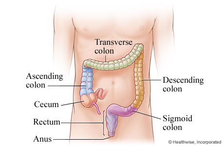
Cancer is most commonly seen in the following regions;
Sigmoid colon (the S-shaped last part) : This is the part of the large intestine that connects to the rectum. It is the most common region. Since stool becomes more solid here, cells are exposed to waste for a longer time, which increases the risk factor.
Rectum : This is the part of the colon closest to the anus. Cancer developing in this region is called rectal cancer, but it is generally referred to together under the heading “colorectal cancer.”
Ascending (right) colon: This is the first region reached by liquid waste coming from the small intestine. Tumors developing in this region usually show late symptoms because the stool is still in liquid form. Therefore, right colon cancers are often detected at a late stage.
Transverse colon : This is the horizontal part connecting the right and left colon. Cancer can also develop here, but it is less common than in other regions.
Descending (left) colon: This is the section where waste moves toward the anus. Tumors here can often present with early symptoms such as constipation, thinning of the stool, and bleeding.
Approximately 40–50% of cases occur in the sigmoid colon and rectum, about 20% in the ascending (right) colon, and the remainder in the transverse and descending (left) colon sections.
What is Colorectal Cancer?
Colorectal cancer includes cancers that develop in both the colon and rectum. It occurs in the lower part of the digestive system due to abnormal cell proliferation. It usually develops when benign polyps gradually turn into cancer. When detected at an early stage, the chance of treatment for colorectal cancer increases significantly.
What are the Symptoms of Colon Cancer?
Colon cancer often does not cause noticeable complaints in the early period. Symptoms usually appear as the tumor grows and can be summarized as follows:
Abdominal pain or cramps
Prolonged diarrhea, constipation, or changes in stool shape
Blood in the stool or dark (tarry) stool
Unexplained weight loss
Persistent fatigue and weakness
Feeling of bloating or fullness in the abdomen
These complaints may also be signs of other health problems. Therefore, it is important to consult a healthcare professional, especially for persistent or unexplained issues.
Causes and Risk Factors of Colon Cancer
Although the exact cause of colon cancer is not fully known, various risk factors have been identified:
Age: The risk increases in people over the age of 50.
Family history: The risk is higher in those with first-degree relatives who have colon cancer; in this case, it is recommended to start screening tests earlier.
Polyps: Polyps that form in the intestinal wall can turn into cancer over time, so their detection and treatment are important.
Genetic disorders: Especially hereditary syndromes such as Lynch syndrome (HNPCC) can increase the risk.
Inflammatory bowel diseases: Chronic intestinal diseases such as Crohn's disease and ulcerative colitis increase the risk.
Lifestyle: Low-fiber, high-fat diets, excessive weight (obesity), physical inactivity, smoking, and excessive alcohol consumption increase the risk.
Certain health conditions: Type 2 diabetes also increases the risk of colon cancer.
How is Colon Cancer Diagnosed?
Today, endoscopic methods are at the forefront in the diagnosis of colon and rectal tumors. With colonoscopy, the standard method, it is possible to directly visualize the inner surface of the intestine and remove suspicious polyps. For a definitive diagnosis, a biopsy (taking a sample from suspicious tissue for pathological examination) is performed. Imaging methods such as computed tomography (CT) can also be used to assess the risk of enlarged tumors or metastasis. The fecal occult blood test is a frequently used screening test.
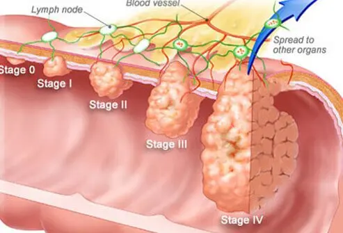
Stages of Colon Cancer and Symptoms by Stage
Stage 0 (Carcinoma in situ): The cancer is still limited to the inner surface of the intestine. Usually, no symptoms are observed.
Stage 1: The cancer is located in the inner layers of the intestinal wall. There may be mild abdominal pain, changes in bowel habits, or a small amount of blood in the stool.
Stage 2: The tumor may extend beyond the intestinal wall but has not spread to lymph nodes. Abdominal pain, significant changes in bowel habits, weight loss, and bloating may occur.
Stage 3: The cancer has spread to nearby lymph nodes. Abdominal pain, weakness, loss of appetite, and more pronounced blood in the stool are observed.
Stage 4: The cancer has spread to distant organs such as the liver or lungs (metastasis). Severe fatigue, persistent abdominal pain, intestinal obstruction, and rapid weight loss may be seen.
What Causes Colon Cancer?
The development process of colon cancer usually occurs when benign polyps gradually turn into cancer. Genetic changes in cells play a role; however, environmental and lifestyle factors are also important. Although a specific cause cannot be identified, avoiding risk factors and participating in screening programs can be protective.
How Long Does It Take for Colon Cancer to Develop?
Colon cancer usually develops slowly, over a period of years. The transformation from a polyp to cancer takes an average of 10–15 years. Therefore, regular screenings are vital, especially for high-risk groups.
Types of Colon Cancer
The vast majority of colon cancers are adenocarcinomas; these tumors originate from glandular cells lining the inner surface of the intestine. Less commonly, other types such as lymphoma, sarcoma, carcinoid, or gastrointestinal stromal tumor (GIST) may also occur. Diagnostic and treatment approaches may vary for different tumor types.
Treatment Methods for Colon Cancer
Treatment is planned individually according to the stage of the disease, the patient's general condition, and the characteristics of the tumor. In early stages, surgical treatment is often sufficient; the aim is to remove polyps and cancerous tissue. In advanced cases, chemotherapy, sometimes radiotherapy, and nowadays targeted therapy or immunotherapy options may be added for some patients. Follow-up and treatment should be managed by a specialized team.
Colon Cancer Surgery
Surgery is the main approach in the treatment of colon cancer. The procedure performed varies depending on the location and spread of the tumor; in early stages, only the polyp may be removed, while in more advanced cases, partial colectomy (removal of a section of the colon along with nearby lymph nodes) may be performed. The extent of surgery and the patient's recovery process depend on the stage of the disease and individual factors.
Possible Risks of Colon Cancer Surgery
As with any surgical procedure, colon cancer surgeries may also have certain risks and complications. These include bleeding, organ injury (for example, urinary tract, bladder, spleen, liver, pancreas, or intestine), leakage at intestinal sutures, infection at the surgical site, and nerve damage. These risks are minimized through pre- and post-operative patient monitoring.
Postoperative Considerations
In the postoperative period, patients may experience mild to moderate pain, and occasionally infection or bleeding. Medications recommended by the physician are used for pain, and antibiotics may be given to reduce the risk of infection. Supporting blood circulation through movement (such as early mobilization and exercises) and adequate fluid intake are important for preventing complications. It is essential to follow the doctor's recommendations and pay attention to dietary advice during the recovery process.
Recovery Process and Length of Hospital Stay
After colon cancer surgery, an average hospital stay of 5–10 days may be required. Even after discharge, recovery may take one or two months. During this period, adhering to dietary recommendations, taking medications regularly, and not missing follow-up appointments are important for a healthy recovery process.
What Can Be Done to Prevent Colon Cancer?
A diet rich in fiber and balanced, adequate intake of calcium and vitamin D, maintaining a healthy weight, regular physical activity, and avoiding smoking and excessive alcohol consumption are important protective factors. Especially after the age of 50, routine screening tests help detect the disease early and improve health outcomes.
Who Is at Risk for Colon Cancer?
Worldwide, colon cancer is more frequently detected in individuals over the age of 50. Individuals with a family history of colorectal cancer are advised to undergo regular screening from younger ages. Various studies have also indicated that a low-fiber, high-protein diet, vitamin D deficiency, and health problems such as diabetes increase the risk.
Where is colon cancer pain usually felt?
It may be felt in the lower or lateral parts of the abdomen, and sometimes as more widespread abdominal pain.
Is a positive stool test an indication of colon cancer?
A positive fecal occult blood test may indicate bleeding in the intestines, including colon cancer. Further examination is required for a definitive diagnosis.
Can colon cancer be detected by ultrasound?
Ultrasound is generally insufficient for the direct detection of intra-intestinal cancers. Methods such as colonoscopy and CT are more effective in diagnosis.
Is colon cancer surgery risky?
As with any surgical procedure, there are certain risks, but with an experienced team and proper follow-up, these risks can be reduced.
Which department should be consulted for colon (intestinal) cancer?
General surgery and/or gastroenterology departments are the specialties to consult for diagnosis and treatment.
How long does colon cancer surgery take?
Depending on the location and spread of the cancer, it may take an average of 2–3 hours.
Can colon cancer be treated with medication?
In advanced stages, drug treatments such as chemotherapy may be applied. However, in early stages, the main treatment is surgery.
Is colon cancer genetic?
Individuals with a family history of colon cancer have a higher risk due to genetic predisposition, but not all cases are genetic.
Does colon cancer recur?
Regular follow-up after treatment is important. In some cases, the disease may recur, so it is necessary to follow the doctor's recommendations.
Are colon cancer and rectal cancer the same thing?
Although colon and rectal cancers share similar characteristics, treatment and approach may differ depending on their location. Both are collectively referred to as "colorectal cancer"
References
World Health Organization (WHO) – Colorectal Cancer Information Page
https://www.who.int/news-room/fact-sheets/detail/colorectal-cancer
American Cancer Society – Colorectal Cancer Guidelines
European Society for Medical Oncology (ESMO) – Colorectal Cancer Clinical Practice Guidelines
US Centers for Disease Control and Prevention (CDC) – Colorectal Cancer Information
The Lancet, New England Journal of Medicine – Current Research on Colorectal Cancer
We have come to the end of our article. Perhaps you or a loved one may be facing this disease.
Just as the universe contains good and bad; beauty and ugliness; Leyla and Mecnun, it also contains both illness and healing.
May what you encounter be the next stop on your journey—a stop of healing.
Knowledge is power. Every step you take with knowledge in any illness will be the most beautiful path to hope.
I wish you and your loved ones healthy and healing lives…
 Health Guide
Cupping Therapy: Effects and Areas of Application from Tradition to the Present
Cupping therapy is known as a treatment method that dates back thousands of years and has been practiced in various cultural traditions. Despite the development of modern medical techniques, cupping therapy continues to attract interest today as an alternative and supportive treatment.
How Is Cupping Therapy Applied and What Is Its Purpose?
Cupping therapy is a traditional practice performed by placing vacuum cups on specific points of the skin. Basically, a mild vacuum is created on the skin, and then small incisions are made to draw out a certain amount of blood. This method is also referred to as "cupping therapy" and has been used for various purposes in different societies.
The fundamental philosophy of cupping therapy: is to improve blood circulation in the body, help eliminate potential toxin accumulations, and support overall health. Additionally, in some cultural beliefs, it is applied to enhance physical-mental balance, reduce stress, and regulate energy flow. In modern medicine, cupping therapy is considered a complementary practice in certain cases.
Possible Effects of Cupping Therapy on Health
Scientific studies suggest that cupping therapy may help with certain musculoskeletal pains and complaints related to circulation. During cupping therapy, it is thought that blood flow in the area increases, thereby accelerating the transport of oxygen and nutrients. This may promote tissue healing and reduce the sensation of pain.
Moreover, there is some evidence that it exhibits a mild anti-inflammatory effect, especially in inflammatory conditions. However, these effects may vary from person to person, and all benefits of cupping therapy have not yet been fully established scientifically. As with any traditional treatment, it is important to consult a healthcare professional before making a decision.
Possible Benefits of Cupping Therapy in the Sacral Region
Cupping therapy applied to the coccyx (sacral region) is generally preferred to alleviate pain around the waist and to increase blood circulation in this area. Additionally, some practitioners state that this method may be supportive in the treatment of neurological disorders. Cupping therapy performed on the coccyx may help relax the muscles in that region and promote tissue healing. Furthermore, in alternative medicine, it is claimed that this region is associated with energetic meridians and may therefore improve the body's overall energy balance. However, it should be noted that such effects are not fully scientifically proven; expert opinion is always a priority.
Cupping Therapy Applied to the Back Region: What Effects Can Be Expected?
Cupping therapy performed on the back region may have a relaxing effect, especially in cases of muscle tension and chronic back pain. It is thought that with increased blood circulation, tissue healing around the spine accelerates and spinal health is supported. It is also suggested that the practice may reduce pain caused by problems such as lumbar and cervical hernia, but more scientific studies are needed on this subject. Individuals considering back cupping therapy are advised to consult their doctors first.
Cupping Therapy on the Legs and Its Possible Benefits
Cupping therapy applied to the leg region is generally preferred as a supportive method for alleviating pain due to circulatory disorders or problems such as varicose veins. In addition, it is thought that it may contribute to the reduction of edema in the leg muscles and the enhancement of tissue healing. Practitioners of alternative medicine also believe that leg cupping therapy has the potential to regulate energy flow. Nevertheless, it should be remembered that this practice may not be suitable for everyone, and expert evaluation should be sought.
Effects of Cupping Therapy Applied to the Facial Region
Facial cupping therapy has become increasingly popular in recent years as a method to support skin health. It is thought that this practice may help achieve a healthier and more vibrant appearance by increasing blood circulation in the skin. Additionally, positive effects have been reported in some individuals in alleviating skin problems such as acne and pimples. However, since the facial region is sensitive, it is not recommended to perform this practice without medical evaluation or expert supervision.
Conclusion and Safety Warning
Cupping therapy is a supportive treatment approach with traditional origins that is applied to different regions. Although it provides positive results such as pain reduction, muscle relaxation, and improved circulation in some individuals, the same benefit cannot be expected for everyone. Especially individuals with chronic diseases or bleeding disorders are strongly advised to consult a doctor. Attention to sterilization during the procedure is also important to prevent the risk of infection.
Frequently Asked Questions
1. How is cupping therapy performed?
Cupping therapy is generally performed by placing cups on the skin to create a vacuum, followed by making small incisions to draw blood. This procedure should be carried out under hygienic conditions and by qualified professionals.
2. In which situations can cupping therapy be applied?
It is most commonly preferred for purposes such as musculoskeletal pain, circulatory problems, and stress reduction. However, it may not be suitable for every individual, and expert opinion should always be sought.
3. Are there scientifically proven benefits of cupping therapy?
Some clinical studies have shown that cupping therapy may help reduce pain and relax muscles. However, more scientific research is needed regarding definitive benefits and comprehensive effects.
4. What are the risks of undergoing cupping therapy?
Application in non-sterile environments may lead to infection, excessive bleeding, or skin wounds. Risks are higher in individuals with bleeding disorders or weakened immune systems.
5. Can cupping therapy be relied upon alone for any disease?
No. Cupping therapy is a complementary method; it does not replace medical diagnosis and treatment. For any ailment, a medical evaluation is required first.
6. Who should not undergo cupping therapy?
Pregnant women, those with bleeding disorders, individuals with active infections, and those with certain chronic diseases should definitely consult a doctor before undergoing cupping therapy.
7. Is facial cupping therapy safe for the skin?
Since the facial region is sensitive, it should be performed under expert supervision and in sterile conditions. It is not suitable for every skin type; a dermatologist's recommendation may be sought.
8. Does cupping therapy cause pain?
A mild stinging or pricking sensation may be felt during the procedure, but severe pain is generally not expected.
9. How many sessions of cupping therapy should be applied?
The number of sessions varies according to personal health status and the targeted complaint. The interval and frequency of application should be determined by expert evaluation.
10. Can cupping therapy be performed on children?
It is generally not recommended for children. In special cases, evaluation by a pediatric specialist is required.
11. What should be considered after cupping therapy?
The area should be kept clean after the procedure, and strenuous exercise should be avoided for a while. Redness and mild swelling are normal; if there are serious complaints, a physician should be consulted.
12. How can I access the most accurate information about cupping therapy?
It is recommended to obtain information from authorized health institutions, specialist doctors, and medical associations regarding cupping therapy. Be cautious against claims without scientific basis.
References
World Health Organization (WHO) – Traditional Medicine Strategy
National Center for Complementary and Integrative Health (NCCIH) – Cupping Therapy
British Medical Journal – Cupping for medical conditions: a systematic review
Shanghai Declaration – WHO Traditional Medicine Strategy 2014–2023
American College of Physicians – Nonpharmacologic Therapies for Low Back Pain